MAC self-build assembly guide

  1. See it go together

    Scroll to watch a self-build MidiPRO 1250 × 750 go together, step by step.

  2. Step 1 of 11

    Check your delivery

    Before starting, make sure you have received all your parts and items undamaged. If anything is damaged, refuse delivery and contact us as soon as possible.

  3. Step 2 of 11

    Lightly de-burr

    Check over each part and lightly de-burr the laser cut tabs and slots. A quick, light pass with a flap disc removes the slag for a tight fit and a flat, true finish.

  4. Step 3 of 11

    Top plate face down

    Begin with the top plate face down on trestles or steels, raised in the four corners, so you can safely reach the underside to clamp.

  5. Step 4 of 11

    Interlock the ribs

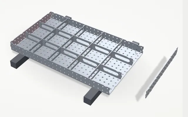
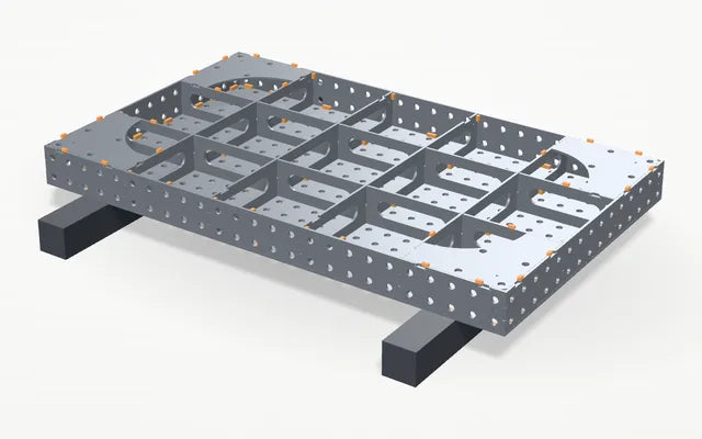
    Interlock the ribs (the sub-frame cross members) as per the slot arrangement, then square them up so there is equal spacing to the edge of the table top.

  6. Step 5 of 11

    Dry fit the side skirts

    Dry fit the side skirts now. This aids construction and squares the sub-frame.

  7. Step 6 of 11

    Clamp it tight

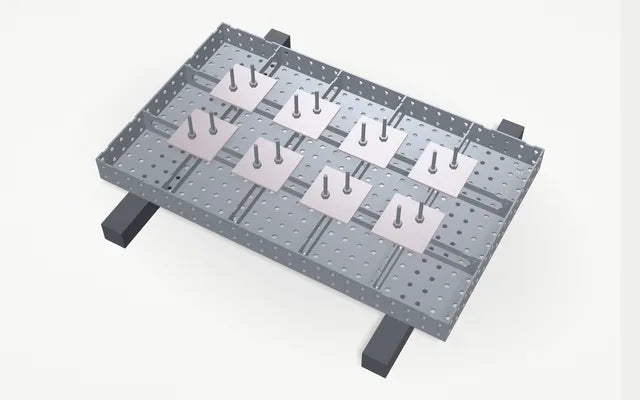
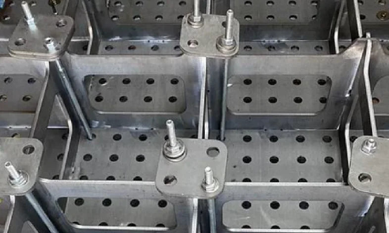
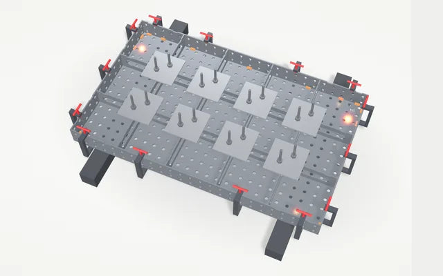
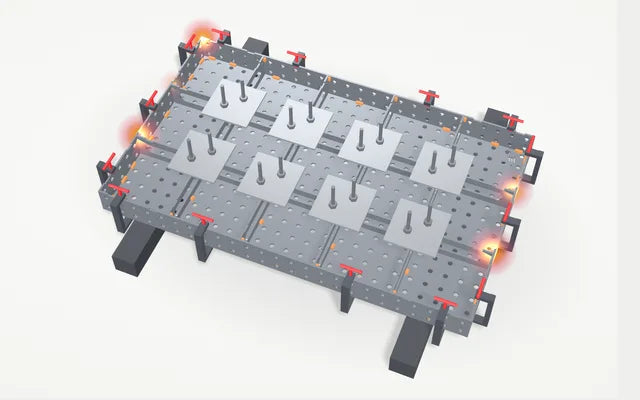
    Assembly plates and threaded bar sandwich the ribs to the top. You want no air gap between the top and the ribs, so the more plates the better.

  8. Step 7 of 11

    Square, align and tack the sides

    Square up the side skirts and align them to the top plate. Clamp them, then tack the sides to the top before welding any ribs.

  9. Step 8 of 11

    Weld the ribs, middle out

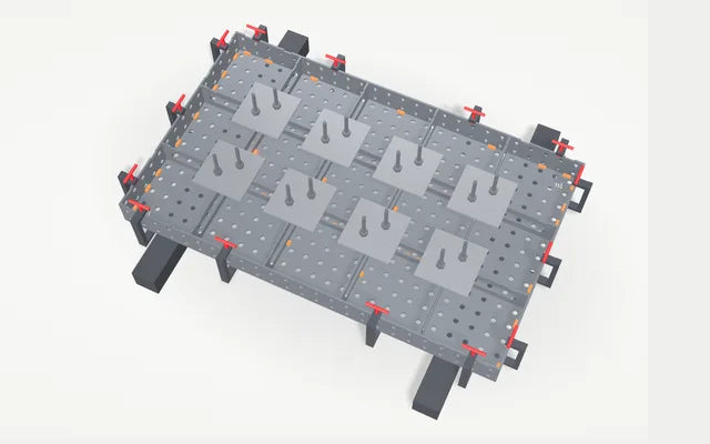
    MIG or TIG. Working from the middle out, place a single 15 mm stitch on one side of the rib only, either side of each cross section, in both directions. Take regular breaks to limit the heat in the top.

  10. Step 9 of 11

    Weld the sides to the ribs

    The sides are only tacked so far. Weld each rib end to the side plate with a single 15 mm stitch on one side, all round the frame, plus a 15 mm stitch in each corner.

  11. Step 10 of 11

    Fit and weld the leg plates

    Drop a leg plate into each corner bay, flush with the side skirts. Stitch weld each plate in place with 15 mm stitches where it meets the ribs and the side skirts.

  12. Step 11 of 11

    Legs, castors, turn it over

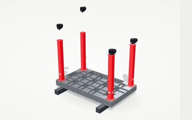
    Bolt each PRO leg on with four M16 × 55 bolts, washers and nuts. Fit the castors, then turn the table over onto them.

  13. Finished

    Built and ready

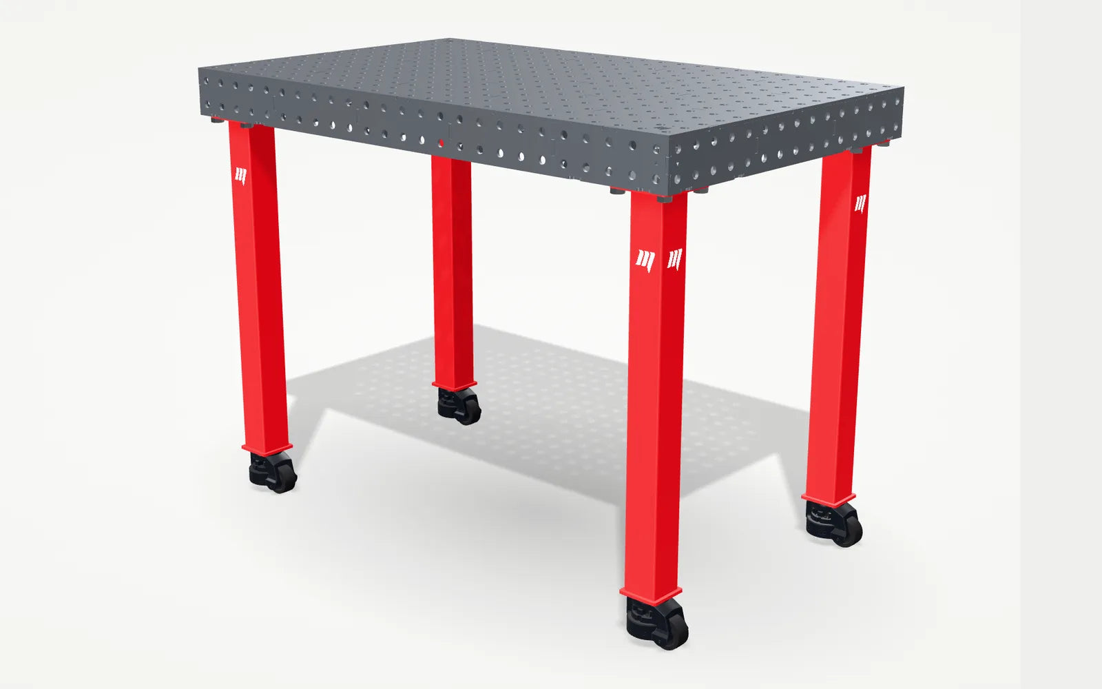
    Your self-build table, square, flat and standing on its castors.

    Configure your table

MAC self-build assembly guide

See it go together

A finished self-build MidiPRO 1250 × 750 welding table on its four castors

MAC SELF-WELD ASSEMBLY GUIDE

BUILD IT RIGHT. KEEP IT FLAT.

0115 MM STITCHESSingle, one-sided stitches
02CENTRE → OUTSpread heat progressively
03KEEP IT CLAMPEDRibs tight to the top
04CHECK. THEN WELD.Square and flat before heat
BEFORE YOU STARTREAD THIS FIRST.

Thank you for choosing a MAC Industries Self Weld Welding Table.

Your table has been precision laser cut in-house in Herefordshire and designed so the individual components locate together accurately before welding. Correct assembly and welding technique are important to maintain the flatness, squareness and accuracy of the finished table.

This guide explains the recommended assembly process.

Before You Start

Please read the complete guide before carrying out any welding.

You will need:

  • MIG or TIG welding equipment suitable for the material thickness
  • Welding helmet and appropriate PPE
  • Welding gloves
  • Clamps
  • Engineer's square
  • Tape measure
  • Straight edge
  • Spirit level
  • Soft-faced hammer or mallet
  • Angle grinder / finishing tools if required
  • A flat and stable surface on which to assemble the table

Important: The surface you assemble the table on can directly affect the finished accuracy of the table. Wherever possible, use a flat welding bench, substantial fabrication table or another known flat surface.

STEPAll 16 steps
CHAPTER 01PREPARESteps 01–03
01

ASSEMBLY STEP

Check your delivery and identify the components

Before starting, make sure you have received all your parts and items undamaged from the delivery company. Your delivery should not have been exposed to the elements, double stacked, opened or received any damage. If it has, please refuse delivery and contact us as soon as possible to resolve this with the delivery company.

Lay out all components and familiarise yourself with their positions. Depending on the model purchased, your Self Weld kit will typically include:

  • Precision laser-cut table top
  • Side panels (side skirts)
  • End panels
  • Internal strengthening ribs
  • Interlocking cross ribs
  • Leg plates and leg mounting components where applicable

Do not begin welding until you are satisfied that all parts are present and correctly positioned.
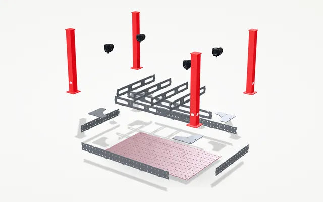
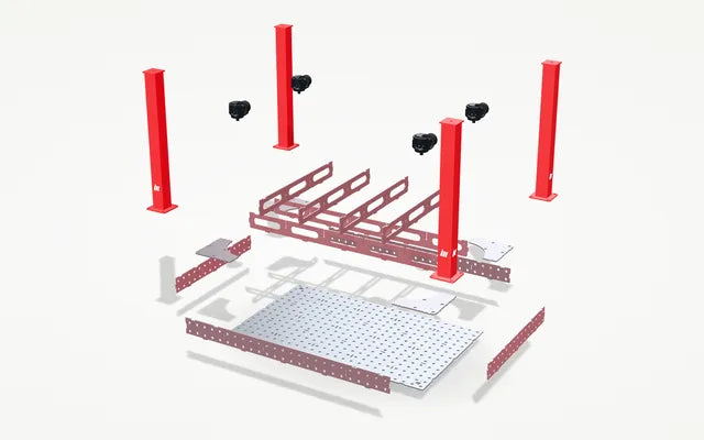
Step 1: every part of a self-weld MidiPRO kit laid out and checked
02

ASSEMBLY STEP

Lightly de-burr the components

Check over each part individually and lightly de-burr the laser cut interfaces (tabs and slots). The fibre laser leaves small amounts of molten steel (slag) on one side of the steel. A quick, light pass with a flap disc grinder (air or angle) removes it, ensures a tight fit and gives a flat, true finished product. We will try to de-burr your parts for you, but this depends on our workshop load.

Remove any loose debris, contamination or sharp burrs that may prevent components from locating correctly.

Avoid excessive grinding of locating tabs, slots or mating surfaces. These features control the position of the table components, and removing too much material can affect alignment.

Step 2: the slotted parts being lightly de-burred
03

ASSEMBLY STEP

Top plate face down

Place the table top working face down on trestles, steels or a pallet: something that raises the plate in the four corners (large tables should also be supported in the centre), so you can safely reach the underside to clamp.

Make sure there is nothing underneath the top that could cause it to rock or distort.

The accuracy of the supporting surface is particularly important at this stage, because the table will naturally follow the surface it is assembled against.

Step 3: the top plate turned face down onto two steels
CHAPTER 02ASSEMBLESteps 04–07
04

ASSEMBLY STEP

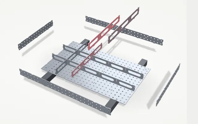
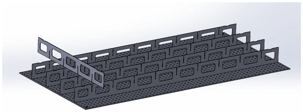
Interlock the ribs

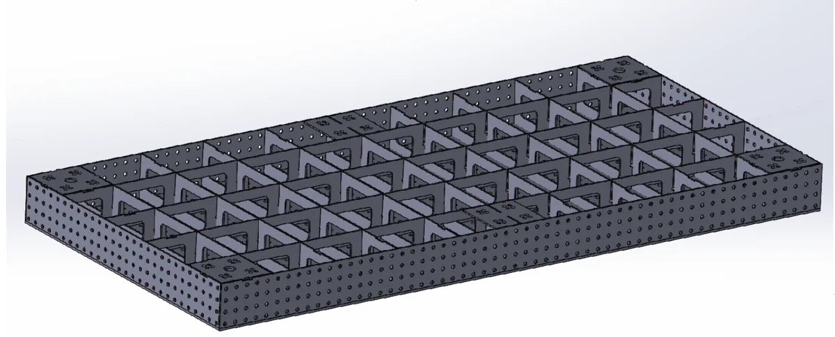
Interlock the ribs (the sub-frame cross members) as per the slot arrangement and dry fit them to the top plate. The lengthways and crossways ribs lock together to create the internal support structure of the table.

Work progressively across the table rather than forcing one complete section together at once. If required, use a soft-faced mallet to gently seat components. Do not hammer directly onto precision-machined or visible finished surfaces with a steel hammer.

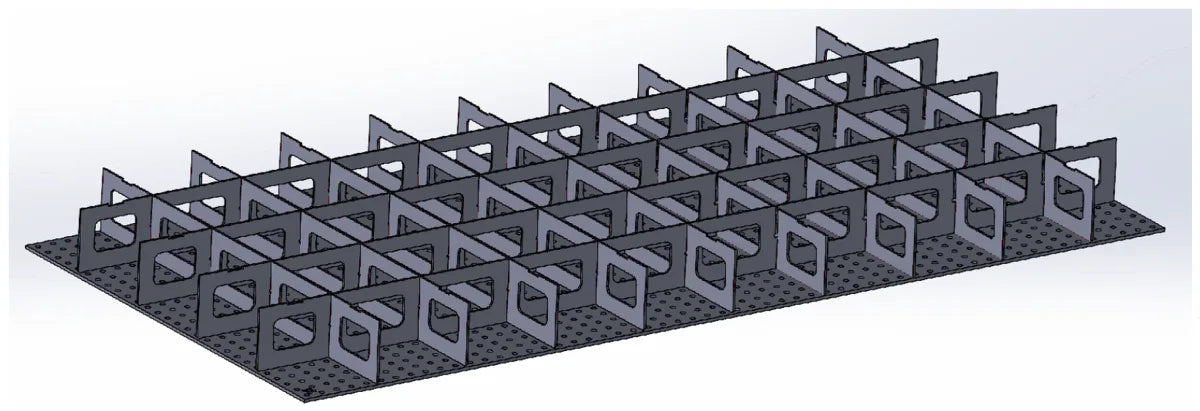
Once all the ribs are slotted together, square them up so there is equal spacing to the edge of the table top, then check that:

  • All ribs are fully seated.
  • Rib intersections are correctly engaged.
  • Components sit square to the table top.
  • Nothing is trapped underneath the assembly.
Step 4: lengthways and crossways ribs interlocked on the top plate
Ribs being interlocked on an upside-down table top
The drawings show a PRO10 2900 × 1400; a MidiPRO goes together the same way.
All ribs slotted together and squared up on the top plate
05

ASSEMBLY STEP

Dry fit the side skirts

If your table has side skirts, dry fit them now around the rib structure. This aids construction and squares the sub-frame.

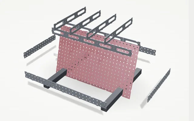
The tabs and locating features should naturally position the components. Use sash clamps or threaded bar to pull the skirt plates tight to the sub-frame, clamping the top plate with the skirt as well, so the panels are fully seated against the table top.

At this stage, do not weld anything.

Step 5: the side skirts slid into place around the ribs
Side skirts fitted around the rib structure
06

ASSEMBLY STEP

Clamp the ribs to the top plate

Before any welding, pull the internal rib structure firmly against the underside of the table top. Use bolts or threaded bar together with the supplied assembly plates (or long bolts, unistrut or something to the same effect) to sandwich the ribs to the top.

Pass the bolt or threaded bar through the table's fixture holes and position the assembly plate so that it bridges the rib underneath. Tighten evenly so the rib is pulled firmly into contact with the top.

Work progressively across the table, clamping the cross sections of the sub-frame throughout. You want no air gap between the top and the ribs, so the more plates the better. The aim is to ensure:

  • The ribs are fully seated against the underside of the top plate.
  • There are no gaps (visible light) between the ribs and the top.
  • The rib structure remains square and correctly located.
  • The top plate remains flat against the assembly surface.

Do not overtighten the clamps. They should hold the components firmly together without introducing distortion into the table top. Tighten the clamping points gradually and evenly rather than fully tightening one area before moving to the next.

Once all clamping points are in, inspect the underside and confirm that the ribs are sitting tightly against the top plate before you carry on.

Leave the assembly plates, bolts or threaded bar in position while you tack and weld, removing them only where you need access to a weld point.

Step 6: assembly plates and threaded bar clamping the ribs to the top
Assembly plates on threaded bar clamping the ribs to the top
07

ASSEMBLY STEP

Square, align and tack the sides

With the table clamped up and the fit checked, square up the side skirts and align them to the top plate. Measure diagonally from corner to corner, and measure both diagonals: the two measurements should be equal, or as close as reasonably possible.

Also check:

  • Side panels are square to the table top.
  • End panels are square.
  • Internal ribs are correctly located.
  • Ribs are firmly clamped against the top plate.
  • The table is sitting flat against the assembly surface.

Make any adjustments now. Once the table is welded, correcting alignment becomes considerably more difficult.

Clamp the sides tight to the top plate with G clamps or similar, then tack the sides to the top before welding any of the ribs. Keep each tack small and controlled, and work around the table rather than concentrating on one area, for example: Front left → Rear right → Front right → Rear left. This spreads the heat evenly and reduces the likelihood of distortion.

Once the sides are tacked, stop and recheck the diagonals, panel squareness, rib alignment, flatness and rib-to-top contact. Small tacks can normally be removed or adjusted relatively easily if anything has moved.

Step 7: the sides clamped square and tacked to the top plate
CHAPTER 03WELDSteps 08–10
08

ASSEMBLY STEP

Weld the ribs, middle out

Do not fully weld the table

MAC Industries Self Weld tables do not require continuous seam welding. The interlocking design provides the structure and alignment; the welds are there to lock the components together. More welding does not make the table better: it simply introduces unnecessary heat and increases the risk of distortion.

MIG or TIG is acceptable. Working from the middle out, place a single 15 mm stitch on one side of the rib only, either side of each cross section, in both directions.

Do not complete all the stitches along one rib before moving elsewhere. Instead:

  • Start close to the centre.
  • Place a 15 mm stitch.
  • Move to the opposite side of the table.
  • Place the next stitch.
  • Progress gradually towards the outer edges.
  • Keep alternating between different areas of the table.

Do not run continuous welds along the ribs, side panels or underside of the table top, and there is no need to join the stitches together.

Step 8: single 15 mm stitches on the ribs, working from the middle out
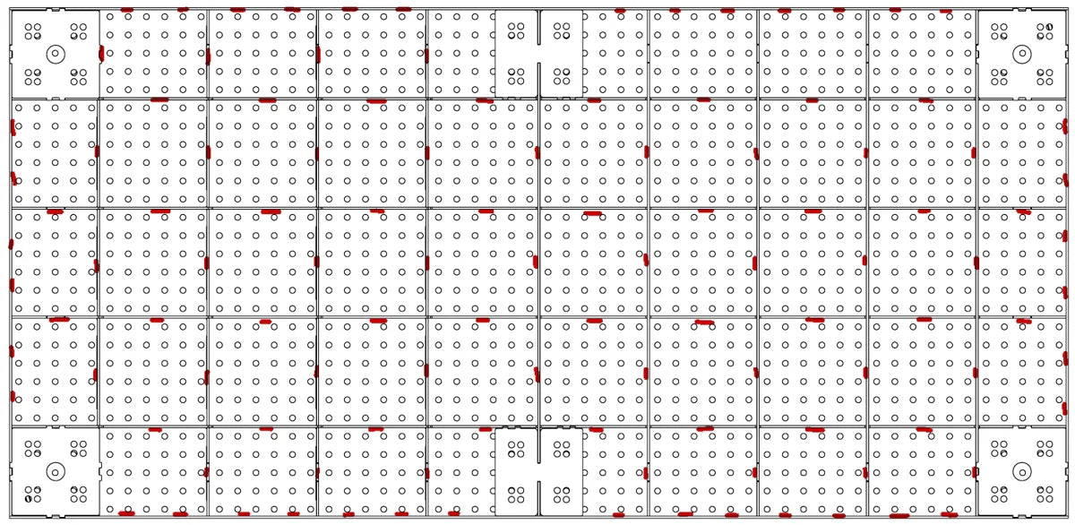
Plan view showing the rough placement of the welds in red
The rough placement of the welds (red).
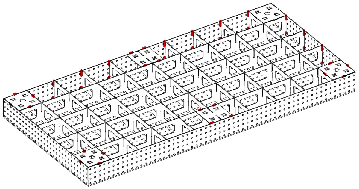
Weld positions on the frame, shown in red
09

ASSEMBLY STEP

Weld the sides to the ribs

At step 07 the side skirts were only tacked to the top. Once the ribs are welded to the top, weld each rib end to the side plate with a single 15 mm stitch on one side, at every point where a rib meets the inside of a skirt, all round the perimeter.

Then place a single 15 mm stitch at the top edge of each of the four corners.

Keep taking breaks to manage the heat, and keep moving around the table rather than finishing one side before starting the next.

Step 9: the rib ends stitch welded to the side skirts, plus the corner stitches
10

ASSEMBLY STEP

Fit and weld the leg plates

With the frame welded, remove the assembly plates and threaded bar, then drop a leg plate into each of the four corner bays, flush with the side skirts.

Stitch weld each leg plate in place with 15 mm stitches where it meets the ribs and the side skirts.

Step 10: a leg plate in each corner bay, stitch welded to the ribs and side skirts
CHAPTER 04FINISHSteps 11–16
11

ASSEMBLY STEP

Legs, castors, turn it over

Once the leg plates are welded and the table has cooled, bolt on the legs. On the MidiPRO, each PRO leg fixes with four M16 × 55 bolts, washers and nuts.

Depending on your selected configuration, fit the appropriate:

  • Adjustable legs
  • Standard castors
  • FM heavy-duty castors
  • Other MAC Industries leg options

Ensure all fixings are securely tightened, then carefully turn the table over onto its castors or feet.

Step 11: the PRO legs bolted on and the castors fitted before the table is turned over
A finished self-weld MidiPRO standing on its castors
12

ASSEMBLY STEP

Level the table

Move the table into its final working position.

If adjustable feet are fitted, adjust each foot until:

  • The table is stable.
  • All legs are carrying load.
  • The working surface is level.

Do not attempt to pull a table flat using the adjustable feet.

The feet should be used to compensate for the floor surface rather than to correct fabrication distortion.

13

ASSEMBLY STEP

Final inspection

Before putting the table into service, carry out a final visual and dimensional inspection.

Check:

  • Table stability
  • Weld quality
  • Side panel alignment
  • Leg fixings
  • Castor operation where fitted
  • Overall flatness
  • All components are secure

Your MAC Industries welding table is now ready for use.

A finished MAC welding table in the workshop
14

ASSEMBLY STEP

Keeping your table accurate

Your welding table is designed for fabrication, but good working practices will help preserve its accuracy.

Avoid concentrating excessive heat in one area of the table for extended periods.

Where possible, allow very hot components to cool before placing them directly onto the table surface.

Regularly clean weld spatter from the table and fixture holes.

A suitable anti-spatter treatment can also help keep the working surface clean and protect the fixture system.

15

ASSEMBLY STEP

Important information

Self Weld tables are supplied as a fabrication kit and require assembly and welding by the customer.

The final accuracy and flatness of a Self Weld table will depend on several factors including:

  • The flatness of the assembly surface.
  • Correct clamping of the internal ribs.
  • Welding technique.
  • Welding sequence.
  • Heat input.
  • Equipment setup.
  • Fabricator experience.

Continuous seam welding is not required or recommended. The table should be assembled using the single 15 mm stitches described in this guide, working progressively from the centre outwards.

For customers requiring a table assembled and welded by MAC Industries, our Ready Made option is available.

16

ASSEMBLY STEP

Need help?

If you have any questions during assembly, please contact MAC Industries before proceeding.

Our team can assist with component positioning, assembly sequence and general product guidance. Call 01432 381 233 or email sales@macindustries.co.uk.

MAC Industries
Precision Welding Tables, Tooling & In-House Manufacturing
Made in Herefordshire, UK

MAC SUPPORT

STUCK MID-BUILD?

If you are unsure about component position, clamping or welding sequence, speak to us before carrying on.